Timing Shack Setup
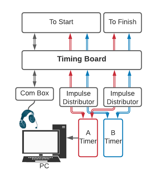
Basic timing shack signal flow for homologated races.
- Equipment Needed
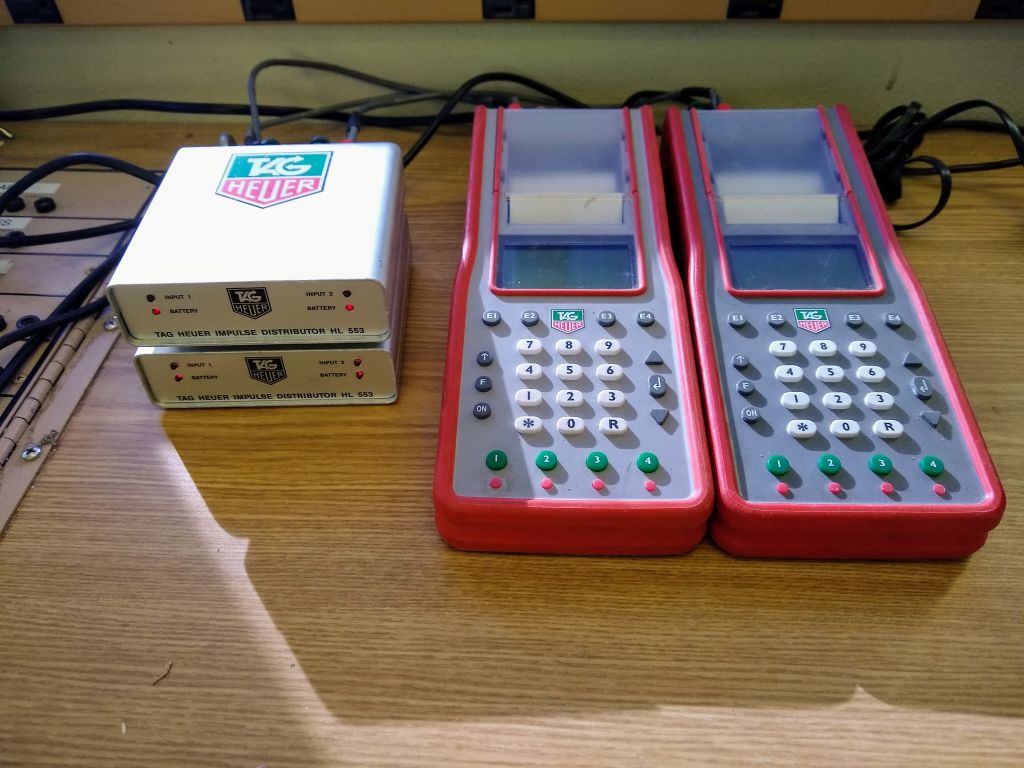
2+ x Impulse Distributor (at least 2 are required. If you are using intermediate times plan accordingly.)
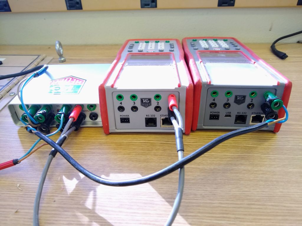
1 x Timing PC (note: a second PC can be connected to System B; this is not required)
1 x Com Box
1 x Pigtail
4 x TAG-to-TAG Cable
1 x RS-232 Cable with USB Adaptor (if using a System B PC, use 2)
The timing shack is where the timing system is tied together. The start and the finish are connected to the electronic timers, and the electronic timers to the timing PC(s). Communications are established between the timer and the starter, and between the scoreboard staff. Accessories such as digital display boards are setup.
Impulse distributors are not required by rule, and some mountains don’t use them. However, the large amount of electrical noise at Mammoth Mountain necessitates their use here. They filter the noise out of timing lines and prevent false impulses.
Table of Contents
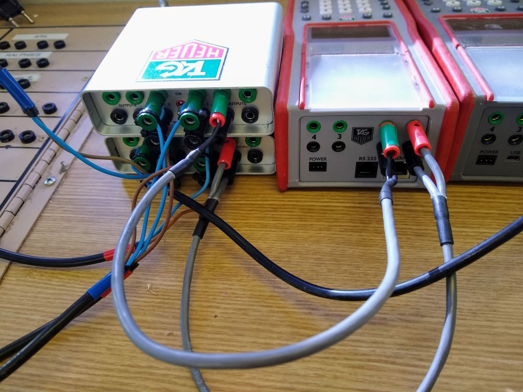
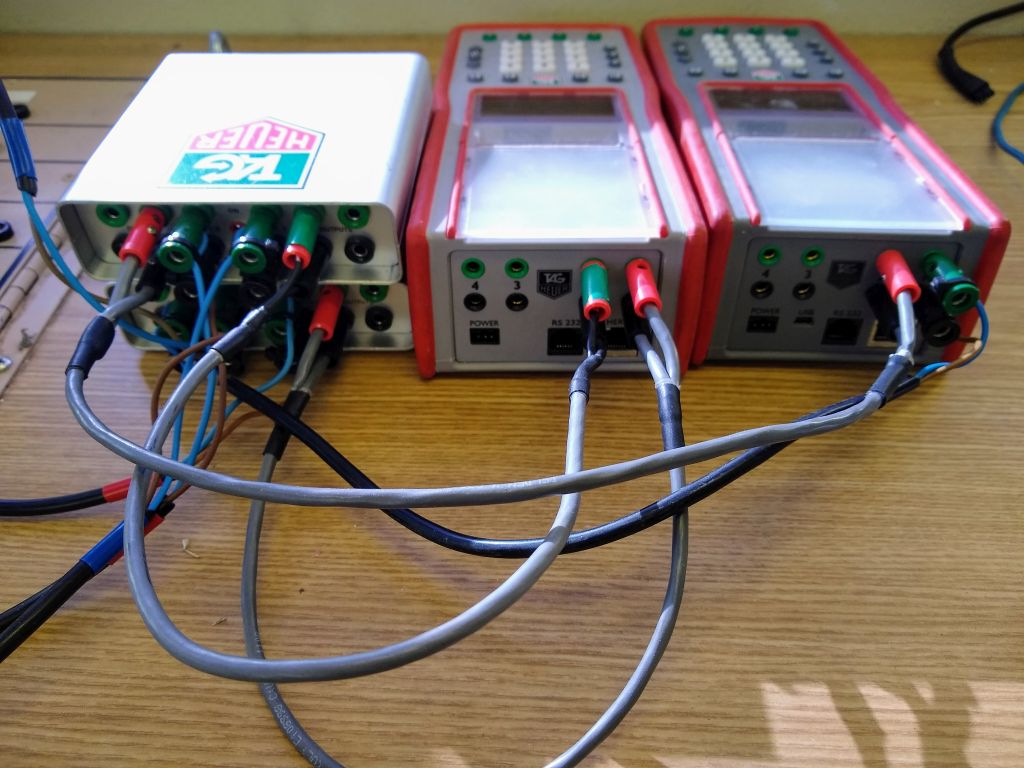
Connect the electronic timers
The first step is to connect the start and finish to the electronic timers. This is made easier by the labled timing boards located in each of the timing shacks. For this example we will use the timing board in the Hilton.
Connect the start
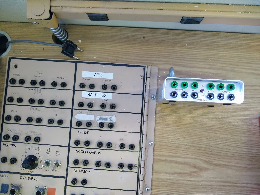
The start distributor next to the timing board.
Step 1
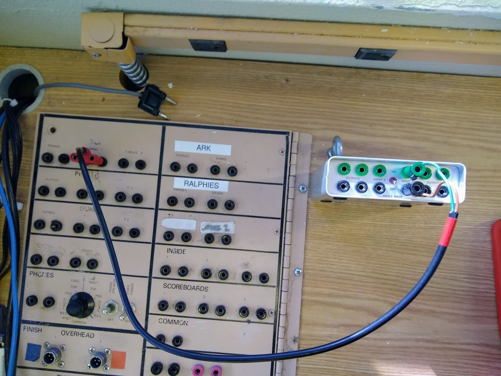
Connect ‘Time 1’ on the timing board to ‘Input 1’ on the start impulse distributor using a Tag-to-Banana Cable. This is the System A start.
Step 2
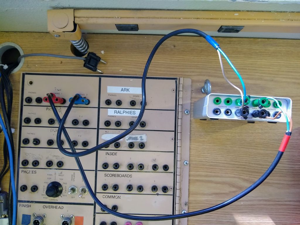
Connect ‘Time 2’ on the timing board to ‘Input 2’ on the distributor. This is the System B start.
Connect the finish
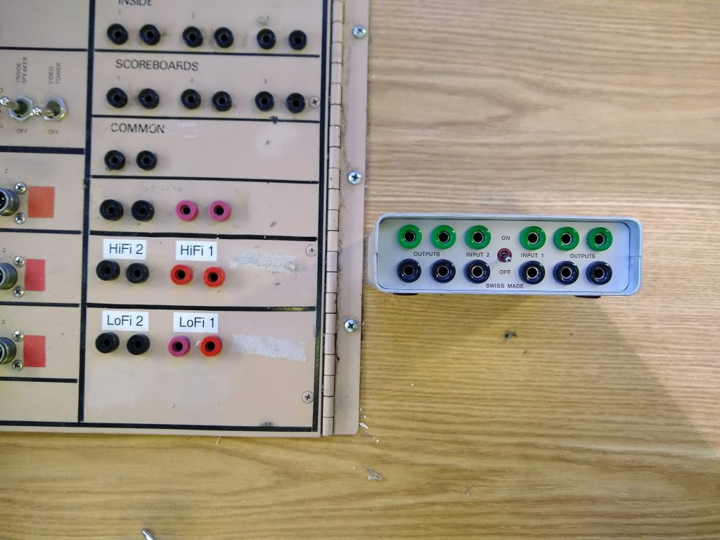
The finish distributor next to the timing board.
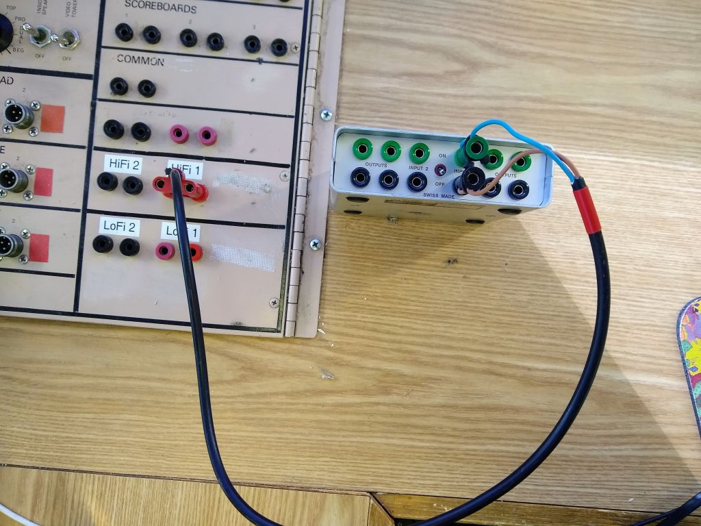
Step 1
Connect ‘HiFi 1’ on the timing board to ‘Input 1’ on the finish impulse distributor. This is the System A finish.
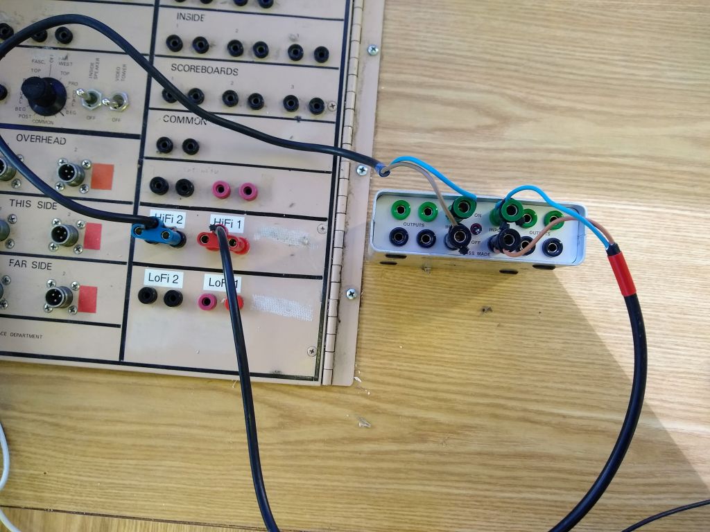
Step 2
Connect ‘HiFi 2’ on the timing board to ‘Input 2’ on the distributor. This is the System B finish.
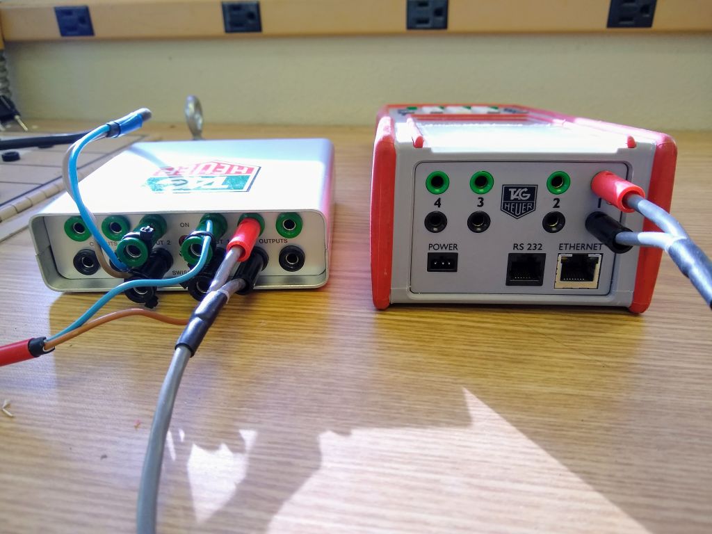
Connect to the timing PC
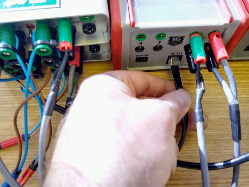
Use the RS-232 cable to connect the System A timer to the timing PC. Plug the telecom cable end into the timer and the USB end into the computer.
Scoreboard Setup

Timing shack signal flow, with digital display board and paper scoreboard connections made